Blade design is one of the most important & complex process in the development of improved and more efficient wind turbines and hence the development of wind industry as such. Advances in aerodynamic design advances has over the years contributed towards that end.
Though ideally, to obtain best results from a perfect blade designed to extract maximum power
from wind, it should have a perfect aerodynamic design. Viewing the requirements of extracting
maximum power at minimum costs pragmatically, leads to necessitating numerous compromises, influenced by various factors.
The major factors that influence design of a practically adequate blade are:
– Economics to ensure costs under control
– Structural Strength to take care of bending stresses (maximum at root), aerodynamic &
structural dynamic loads
– Noise & Aesthetic considerations
– Choice of materials; carbon versus fibre glass; availability of desired material
– Manufacturing Processes adopted
The blade needs to be robust enough to survive forces acting on them due to the variability of wind, to include varying wind velocities, facing gusty conditions to an extent, centrifugal & centripetal forces and other conditions that are rarely optimal.
Over the years, with the continuous development of larger & more efficient Wind Turbines, a variety of blade designs & materials have got introduced, mainly through trial & error, resulting in the most popular 3-bladed composite blade designs, each better than the other.
The choice of blade aerofoils, chords, twist distribution, blade tip & root configurations, use of spoilers, use of vortex generators for noise control &/ or enhancing aerodynamic efficiencies, are a result of compromises being made from conflicting considerations. The dictating requirements could be, need for blade stiffness/ flexibility, Solidity of rotor disc, aerofoil thickness, maximising lift coefficients, minimising drag, roughness tolerance. To sum it all, the design considerations are numerous and at times conflicting leading to the need for an intelligent compromise.
The aerofoil is the foundation of wind turbine blade designs & hence its optimisation goes a long way in achieving the three objectives of aerofoil design, namely, aerodynamic performance of the blade, Noise control & its structural robustness.
Selection of Aerofoil Sections along the Blade Length
In the early stages of development of wind turbine blade designs, NACA series of aerofoils, which were basically developed for use in aviation industry were used mainly because of their inherent design of high lift Coefficients and low Drag Coefficients, (High Lift to Drag ratio). However, it was quickly recognised, that there were numerous drawbacks which glaringly stood out while they were being used for high performance blade designs wind turbines. This led to the development of a number of specially designed aerofoils for wind turbines. These included:
- American S Series airfoil
- Dutch DU Series
- Swedish FFA-W series
- Danish RisF series airfoil
While a number of research papers are available, describing the utility of each of the aerofoil sections, their suitability for use at specific Tip speeds, Lift coefficients, L/D ratios, structural properties, and noise characteristics, in order to grasp the nuances of each of these designs, certain basics of loads on a wind turbine blade and specifically an aerofoil section would be necessary and the same are briefly introduced in subsequent paragraphs.
Forces Acting on the Blade

Fig 1 : Forces Acting on Blade Section of a Horizontal Axis Wind Turbine
Figure 1 above depicts a wind turbine, viewed from top. (Plan View). Details are explained below:
– The direction of rotation is clockwise as seen from front end, as indicated.
– Aerofoil section of one blade has been shown.
– As it is understood, the turbine is designed to face the wind squarely and the ambient wind velocity vector impinging the aerofoil section is shown by the blue arrow.
– Since the blade is rotating, the instantaneous tangential velocity of blade is considered. The relative wind velocity vector due to motion of the blade will be opposite to the blade tangential velocity vector.
– Resultant of the two wind velocity vectors impinging on the aerofoil section, (the actual relative velocity vector) is shown as a red arrow.
– The angle between the chord of the aerofoil section and the relative velocity vector is called the angle of attack. (⍺)
– Angle of Attack has a great significance on aerodynamic performance of an aerofoil. A brief
bringing out its significance is explained subsequently.
– Lift generated is perpendicular to the relative wind velocity vector, and perpendicular to the lift is the drag. (in the same direction of the relative wind velocity). The same are depicted in Figure 1.
– Resultant of Lift & Drag forces is the “Net Aerodynamic Force on Blade”.
– This “Net Aerodynamic Force on Blade” is resolved into two mutually perpendicular forces. These are (a) the Torque Force that Rotates the Rotor & (b) the thrust force, which acts along the axis of rotation. This force is the design element for finalising the bearing design.
Significance of Angle of Attack
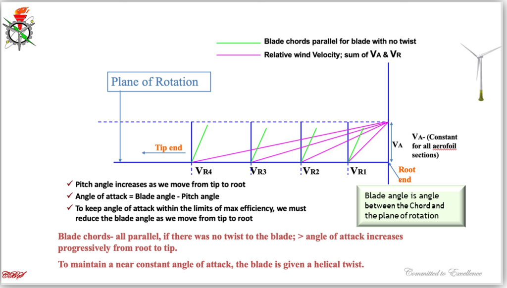
It can be appreciated that the aerofoil sections move at faster speeds as we move from root to the tip of the blade (V=r w). While the ambient wind speed remains the same. The effect of this would be, that the angle of attack at various aerofoil sections all along the length of the blade from root to tip will progressively change. The necessity of giving a twist to the blade as we move from the root to tip of the blade is shown in the Figure 2 below.
If there is no twist, the angle of attack would have large variations all along the length of the blade and hence, only a section of the blade will generate optimal lift and the most of it will be either stalled of producing low lift and therefore working at sub-optimal levels. By giving the twist, the most efficient angle of attack, (see Fig 3) for each aerofoil section all along the blade length is obtained. This leads to an overall performance level of the blade to be enhanced/ optimised.

Fig 2: Showing the necessity of twisting the blade
The production of lift force due to the aerodynamic shape of the blade depends on a number of factors like the blade profile, shape, thickness, camber, aspect ratio and the surface finish of the blade, which must be in consonance with the designed rpm, tip speed ratio, solidity and the magnitude of lift coefficient.

Fig: 3 Indicating that an aerofoil section performs at peak performance levels (at CL max) for a very narrow range of the value of Angle of Attack. Beyond the max level it stalls and before that the blade efficiency rapidly drops.
The complete mechanism of production of lift and various other modifications to enhance blade aerodynamic performance will be covered in my next blog.


